After successfully loading the drawing, it should appear as the following:

This background drawing shown above displays the following:
•A coordinate grid, set up for the southern hemisphere (Y increases to the west, X increases to the south).
•An existing system consisting of Catchments, an Outfall, Bulk Conduits, Conduit network and ground level balancing tank.
•A river and contours varying from 100m a.s.l. to 180m a.s.l.
•A potential future large catchment to the south of the stormwater network, as well as a potential future supplementary conduit system to serve this catchment.
•Potential reinforcements to the system to accommodate the large catchment and potential growth in the stormwater load of the existing system.
Before we start using this drawing, we must make sure that it is geospatially correct.
Move the cursor to the top RH corner of the grid at southern hemisphere coordinate marked as Y0, X0. At the top RH of the program window you will see that the drawing coordinate is 1000X, 1000Y. This means for starters that the drawing is not in the correct location.
Move the cursor to the bottom LH corner of the grid at southern hemisphere coordinate marked as Y13500, X9000. At the bottom LH of the program window you will see that the drawing coordinate is -5750X, -3500Y. This means two things:
•The drawing is in the world coordinate orientation with X increasing to the east, and Y increasing to the north.
•The drawing scale is incorrect, since the delta distances are only half of what they should be:
o1000X -( -5750X) = 6750X instead of 13500
o1000Y - (-3500Y) = 4500Y instead of 9000
The drawing will be geospatially fixed in two steps.
Step 1 (the hemisphere):
CAD systems orient their natural coordinate systems in a normal Cartesian plane, with the X-axis pointing to the right, Y pointing up, and Z coming out of the screen. In the Southern hemisphere, coordinates are represented in quite a different manner, with the X axis pointing downwards from the equator, and the Y axis pointing left of the Zero (Greenwich) meridian. Because this is not the natural orientation of the CAD, a User Coordinate System (UCS) has to be defined that causes all the coordinates to be translated automatically from Southern Hemisphere coordinates to CAD friendly World Coordinates (i.e. regular Cartesian).
The XYZ coordinates of the drawing are displayed in the bottom RH corner, and the UCS symbol in the bottom LH corner normally shows the directions of the X and Y axes. The coordinates are always handled in a “world” system and the drawing is always properly orientated, but if you are working in the southern hemisphere (e.g. South Africa) like the author of this drawing has done, and would like to have the Y axis on the horizontal increasing to the west, and the X axis on the vertical increasing to the south, you should first click in an open space of the drawing (effectively making sure nothing is selected) and then set Southern Hemisphere by editing the CAD properties in the Edit box (located at the top RH corner) as follows:
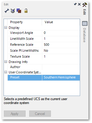
The coordinates (according to the Southern Hemisphere Surveyor coordinate system) are displayed on the bottom right corner of the status bar. Note how Y now increases from East to West, and X from North to South.
Step 2 (Scale and Location):
Often when drawings are imported or converted between systems or projects, they get reorientated for whatever reason. This is also currently the case, since the coordinates of the two known points still do not match those indicated on the status panel (they are substantially out in both the x and y directions). HydroSWMM provides a function to re-orientate these drawings (or portions of them) to their proper coordinates, given that the user knows the exact location of 2 points on the drawing (as is known from the grid).
Since the two known points should be indicated per mouse click on the drawing, it is important that the snap settings are set up correctly. This can be achieved via CAD > Tools > Snap Settings to enter the Snap setup dialog box. Ensure that snap settings are activated (Snaps On box should be ticked at the top left) and that the boxes Center, Vertex / End Point, and Intersection are at least ticked. The click the X at the top right:
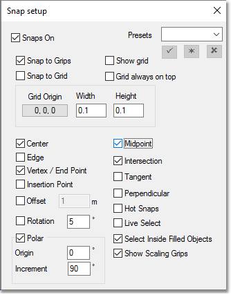
Then select CAD > Tools > Fix to Coordinates. You will then be prompted to convert the entire drawing. Click Yes. If you did not receive a prompt a selection was active when starting the function. Exit the function and make sure nothing is selected before continuing.
The following input template will appear (just below the HydroSWMM main menu, and with initial blank boxes). The screen-shot below already contains the results when following all the steps indicated below:

Fixing first known point (top RH corner of the grid):
Click on the mouse pointer icon situated to the right of the top left row of three text boxes (1). Then zoom to the top right of the drawing by rotating the mouse wheel. Click on the first known point (in the top RH corner of the grid). The original Y-1000, X-1000 coordinate of the first known point will hereby automatically be filled into the “Move From” text boxes.
On the keyboard, type 0, 0, 0 into the corresponding “Move To” text boxes for this first point (2), which is the actual real world coordinate for this known point (as also annotated on the drawing).
Fixing second known point (bottom LH corner of the grid):
Click on the mouse pointer icon situated to the right of the bottom left row of three text boxes (3). Zoom to the bottom left of the drawing by rotating the mouse wheel. Click on the second known point (in the bottom LH corner of the grid). The original Y+5750, X+3500 coordinate of the second known point will hereby automatically be filled into the “Move From” text boxes.
On the keyboard, type 13500, 9000, 0 into the corresponding “Move To” text boxes for this second point (4), which is the actual real world coordinate for this known point (as also annotated on the drawing).
The transformation of the two points as set up above will be visible in preview on the CAD screen:
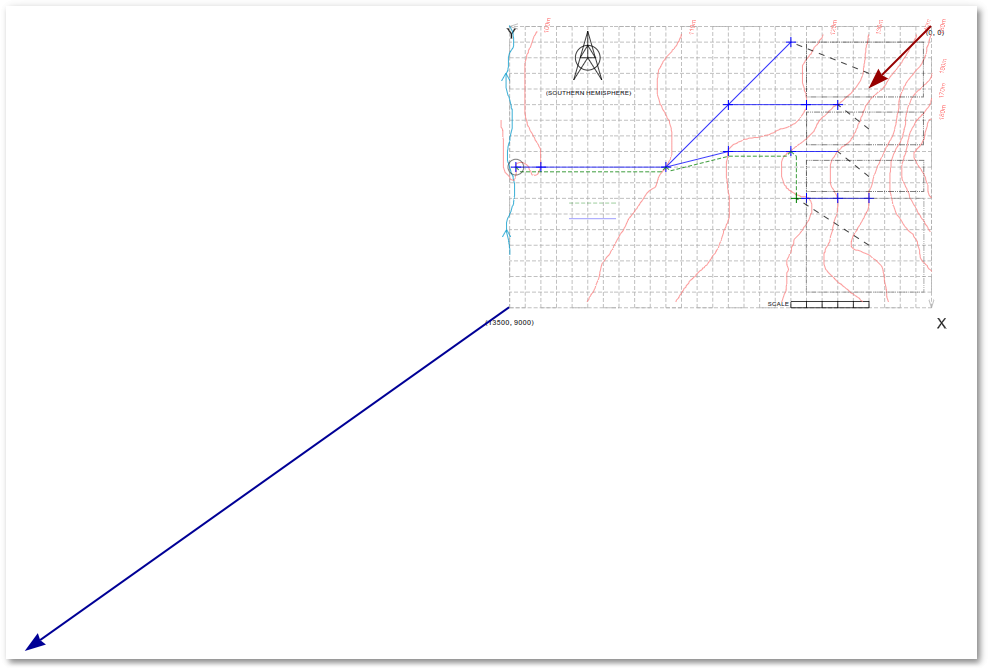
Finally click the dark green ("Yes") tick mark (5), located at the bottom right of the input template, to execute the coordinate transformation.
The drawing is now fixed to the proper coordinate system (select View > Zoom to Drawing Extents to zoom to the new drawing extents). This can be verified by moving the mouse pointer to the two known coordinate points - the given coordinates will now match with those in the bottom right hand boxes of the status panel.