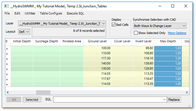
The system data is now complete, except for one omission, namely the ground elevations of the junctions. For a small system like this one, it is feasible to individually edit each of the junctions. However, this becomes impossible when dealing with large systems. For this reason, a built-in module to automatically update ground elevations was developed, and will be demonstrated in this tutorial. It is based on the same principles used in triangulation routines found in most digital terrain modelling (DTM) software.
Firstly, a surveyed “spotshot” file covering the system area is required for the DTM routine. A typical file will have thousands of points, with a coordinate and elevation for each. The spotshots are normally done on a fixed grid of (say) 50m x 50m. The denser the grid, the more accurate the DTM. The survey file for this tutorial is Documents\GLS\HydroSWMM\HydroSWMM - Tutorial DTM.YXZ. You can view this file using any text editor like Windows’ Notepad or Sublime Text. For this example file, a grid density of 500 m x 500 m was used. The first few lines in the DTM data file look like this:

Create now the internal DTM model in HydroSWMM via DTM > Load DTM and browse to the above survey file.
The DTM is then built in memory. You can verify the extent of the DTM by selecting DTM > Show Points and then select an existing empty layer, such as layer "0" (also ensure that layer "0" is visible). The elevation of individual points comprising the DTM mesh can be checked by hovering over them and reading the YXZ values at the bottom right of the screen. You can now hide layer "0" again.
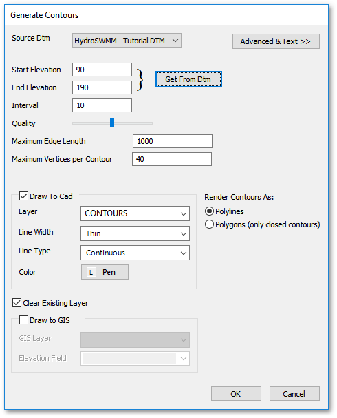
You can create contours using DTM > Generate Contours which will open the Generate Contours dialog box. In this dialog box, click the Get From DTM button to set the start and end elevation and then click OK to draw the contours.
Finally, to update all the node elevations, go to DTM > Update Model Elevations > For All > Nodes and Links. You will receive a warning that not all nodes could be updated, specifically Junction 1 (the Outfall). Remember to check the bottom status window for the list of nodes with an issue. As the node fell outside the area of the DTM, its ground elevation must be set manually to 95 m by click-selecting the node and manually entering the ground elevation in the Elevation (m) field of the Database box:

The remaining task now is to assign an invert level to each Junction. Highlight the Invert Level column, and populate the field with '0's by entering '0' into one of the records. For this example we will be using a constant Max Depth of 1.2 meters below the cover level. Select the Max Depth column so that all records are highlighted and enter '1.2'. This will auto-update the Invert Level fields for all the records. For the single outfall, manually enter an Invert Level of 93.8 m.